Platform review and sensor intake
Sensor stack, package geometry, optical path, and camera constraints are reviewed to define the integration plan and risk points for the target platform.
POLARX PHOTONICS
Case Study
Filter-array bonding, calibration, and ISP integration
PolarX Photonics aligns and bonds pixelated filter arrays to arbitrary image sensors, then develops the calibration and ISP needed for usable system output. This case study summarizes a Sony IMX990-based SWIR polarization camera built through that workflow.
Case-study platform
Sony IMX990-AABJ
SVS-VISTEK exo990MGE
PolarX scope
Precision alignment and bonding, internal process software, calibration, customer software / ISP, and deployment support
Workflow
Each camera platform requires its own mechanical, optical, and software path. The workflow below summarizes how PolarX adapts pixelated filter arrays to a given sensor platform, including systems that require cover-glass removal before bonding.
Sensor stack, package geometry, optical path, and camera constraints are reviewed to define the integration plan and risk points for the target platform.
If the cover glass is not removable, PolarX develops dedicated removal tooling and SOPs using a UV/CO2 laser ablation system, followed by cleaning and preparation.
Custom fixtures and camera-platform-specific tooling are developed for handling, registration, bonding, and any required rework on the target hardware.
The bonding process is defined for the selected pixelated filter array, including adhesive stack, placement strategy, and process controls for repeatable integration.
Alignment is performed in a cleanroom using realtime sensor feedback, ROI metrics, and process control to push registration as far as the sensor geometry allows.
After bonding, optical and mechanical performance verification is performed to confirm registration, inspect the assembly, and benchmark the bonded hardware baseline.
Calibration files and ISP processing are developed and tuned to convert the bonded stack into stable outputs and improve delivered effective contrast.
Customer software integration, visualization, controls, and export workflows are developed for the target camera platform and application.
Software Stack
The first interface shown is internal-use process software for alignment and bonding, using realtime sensor feedback to optimize placement before final attachment. The second is customer-facing camera software and ISP tooling, which PolarX can develop and customize for the target system.
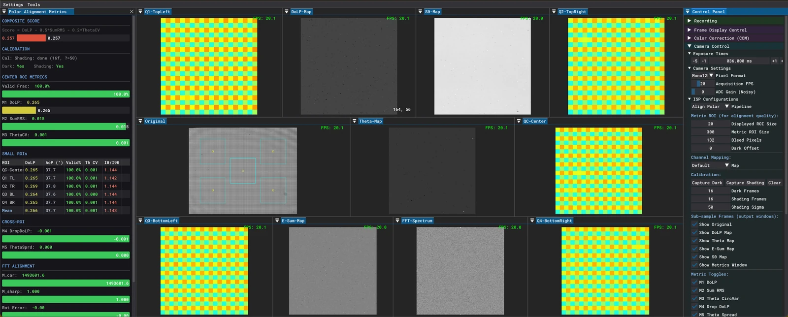
Internal use only
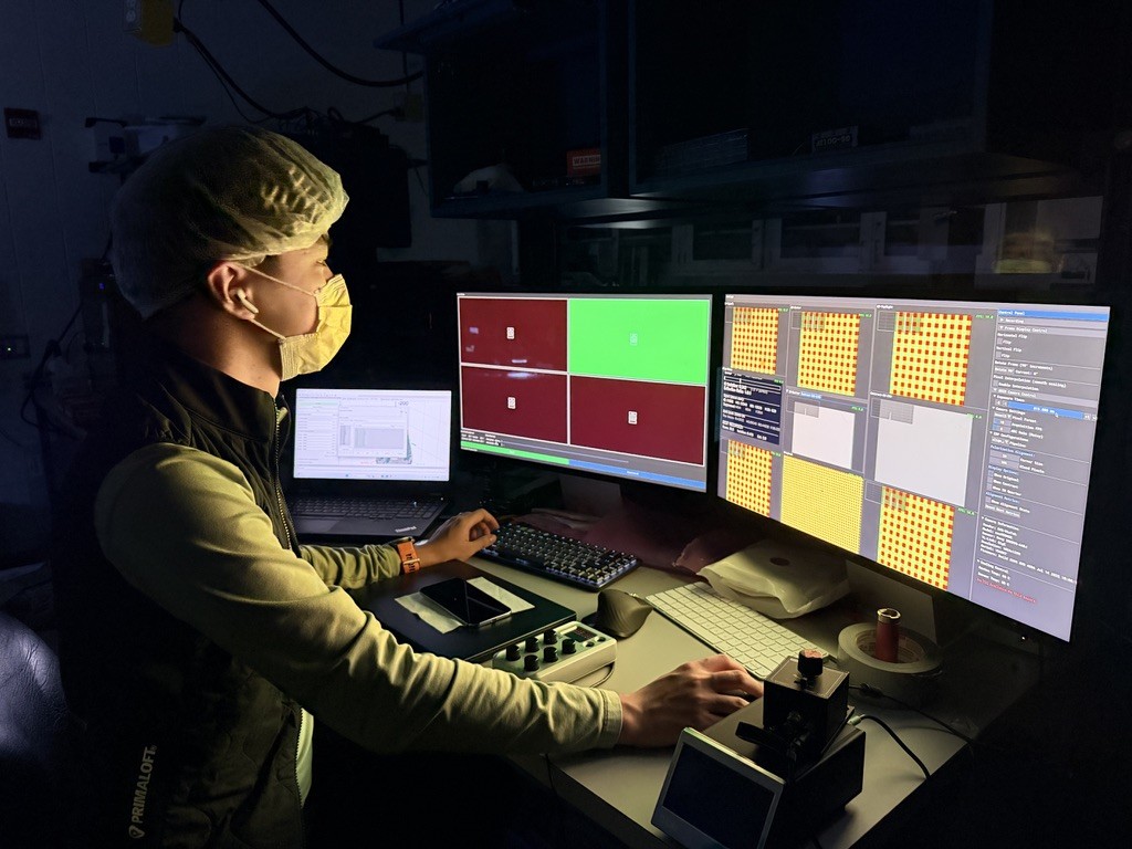
This environment is used during process development and assembly. It uses realtime sensor feedback, ROI metrics, and spatial checks to drive alignment toward the best physically attainable registration.
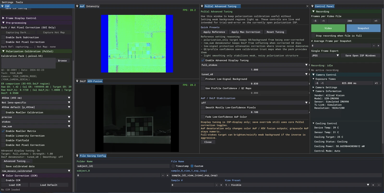
Customer software / customizable
Calibration loading, visualization, tuning controls, and export tools can be developed and customized for the customer workflow and target application.
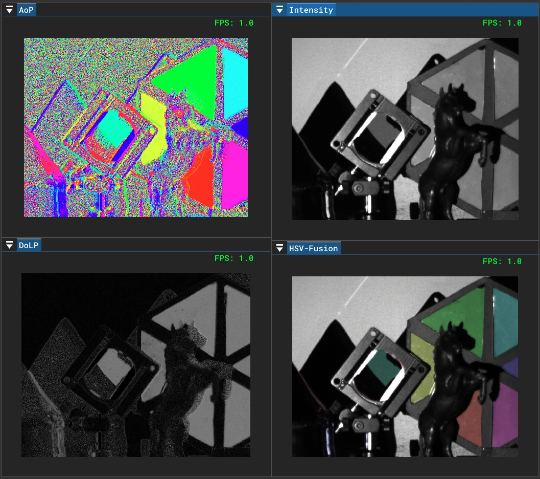
Live Demo
The same platform can deliver synchronized polarization-derived views such as AoP, DoLP, intensity, and HSV fusion within the software stack.
Performance Review
The raw plots show the bonded hardware baseline after physical alignment has been optimized. The calibrated plots show the additional system-level gain from calibration files and ISP processing.
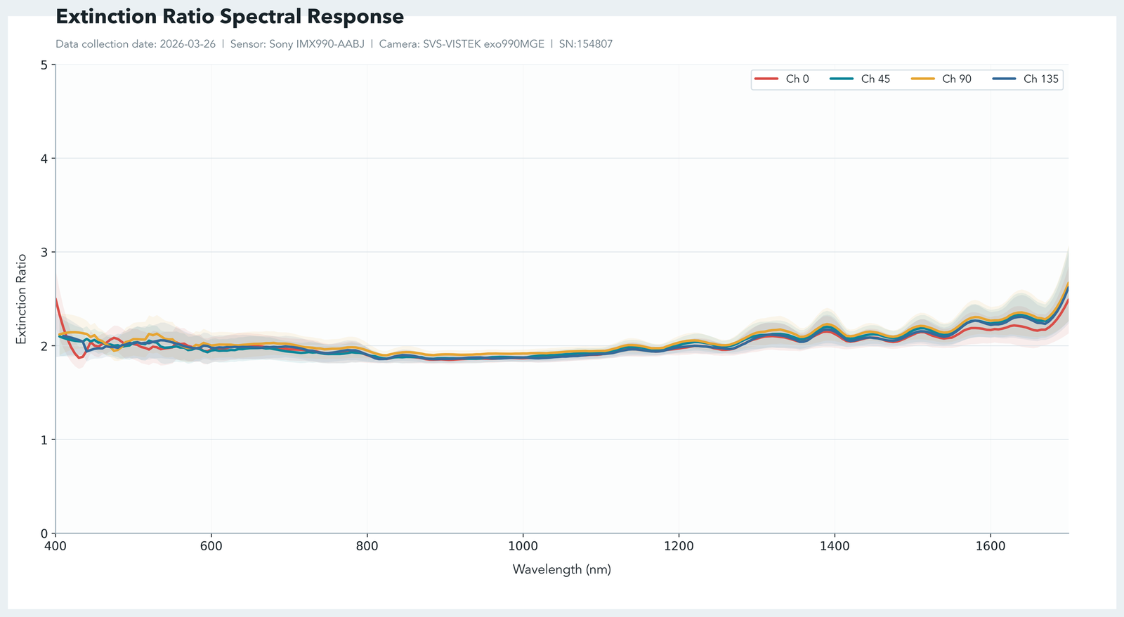
Baseline ER of the bonded sensor and filter stack before calibration files and ISP are applied.
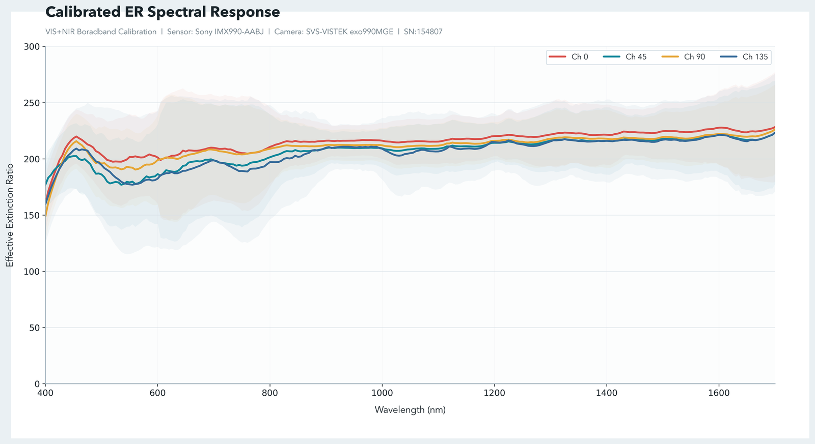
Calibration files and ISP raise delivered effective ER and contrast ratio on the bonded hardware baseline.
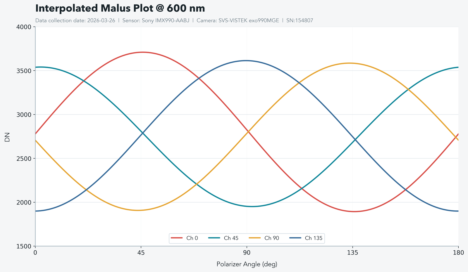
The raw response shows the bonded hardware baseline with usable four-channel sinusoidal separation.
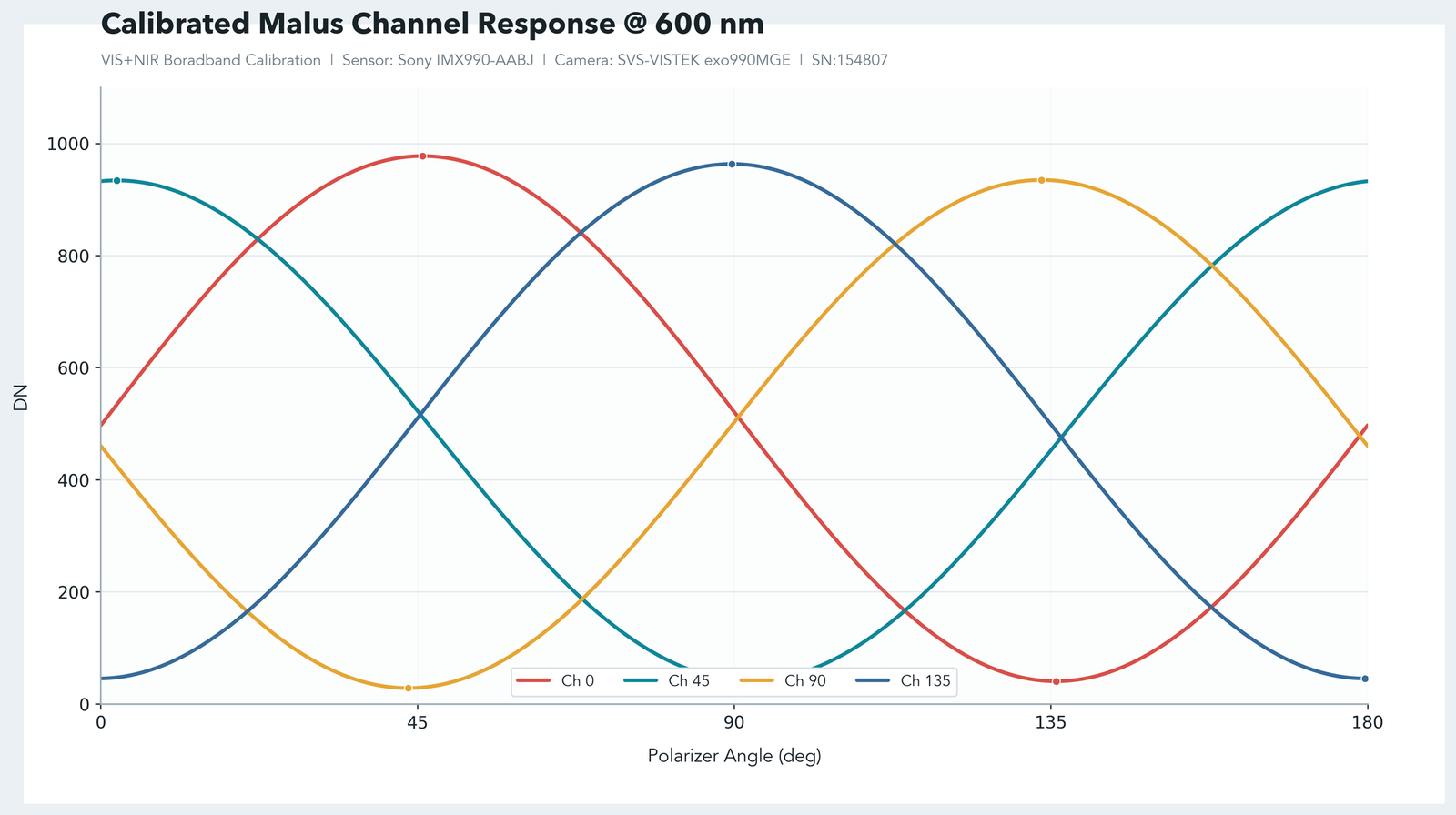
Calibration files and ISP preserve channel separation while improving the delivered system response.
Platform Extension
This IMX990 case study is one example of a broader process. The same bonding, calibration, and software approach can be adapted to other sensors, pixelated filter arrays, and customer-specific imaging pipelines.
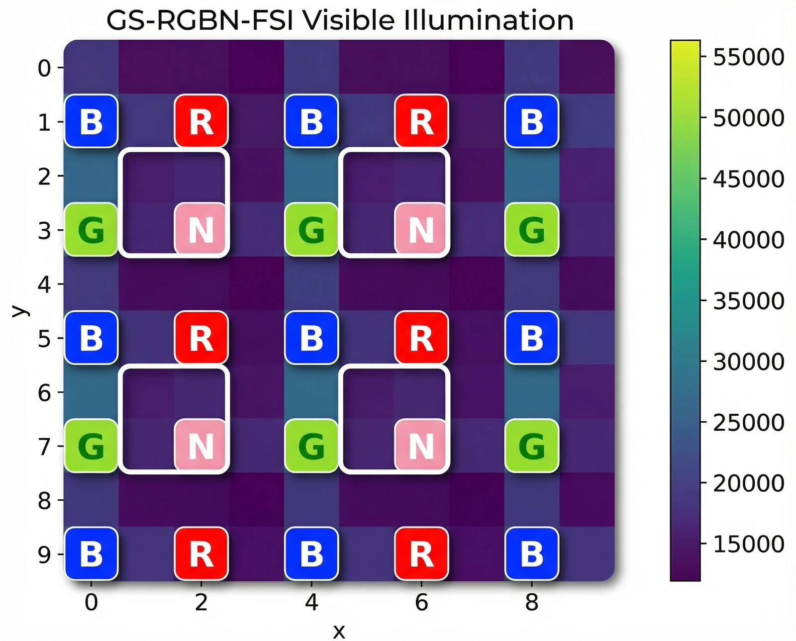
Example of a visible-band pixelated filter array architecture beyond polarization imaging.
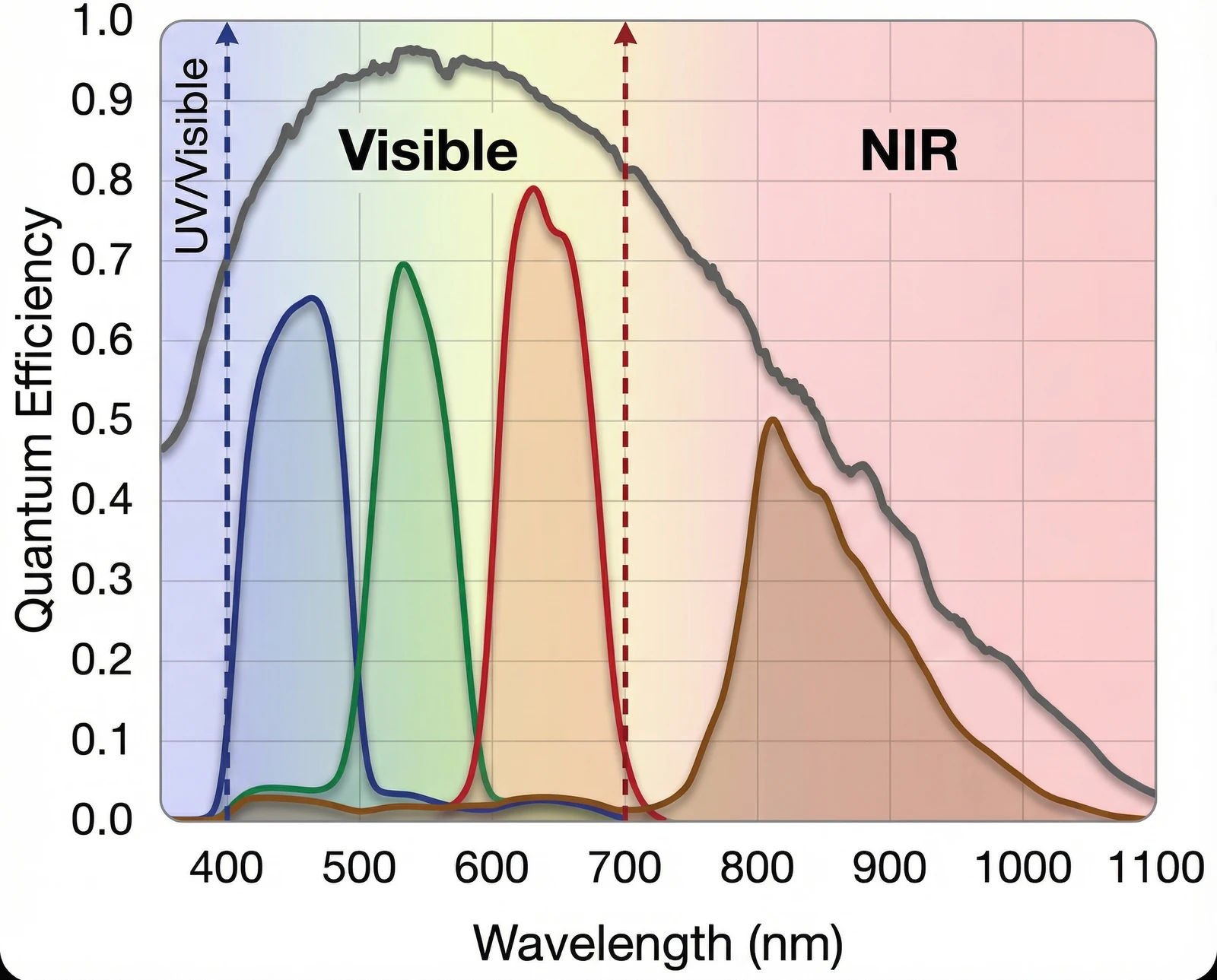
Example broadband response spanning visible and near-infrared operation for non-polarization filter-array systems.
Contact
For technical follow-up, program discussion, or application review, please contact:
Jonathan Zhu
Co-Founder | Imaging Systems & Photonics Engineering
PolarX Photonics
Champaign, IL, USA